Technical data
|
PRIVATE DRAINAGE - SEPTIC TANKS & CESSPITS In remote rural areas without the luxury of public sewers, you traditionally had a simple choice when it came to dealing with foul waste: you had to either build your own private sewage works or be prepared to empty a lot of buckets. The old-fashioned cesspool (or cesspit) comprised an underground chamber storage tank into which your foul ‘solids’ and ‘soil’ waste would be flushed. It would need to be located some way out in the garden (at least 7m away from the house). Construction would typically be the same as a manhole, of rendered brick walls on a concrete base, but with a reinforced concrete sealed lid for access. The general idea is that, over time, the solid waste settles at the bottom and the relatively clear liquids are drained off safely into a handy nearby field by way of a land drain, rather like a soakaway. When full, cesspits require emptying by a suction tanker. But in order to reduce the need for frequent emptying (and the associated cost) one popular illegal dodge was to wait until the District Surveyor had approved the new structure and safely departed, and then ‘accidentally’ knock out one of the bricks so fluids could seep away into the ground. Perhaps it wasn’t fully appreciated that leaking cesspits had, not so long ago, been the cause of fatal cholera epidemics as a result of contaminated drinking water in nearby wells and streams. Today, prefabricated plastic or GRP units are available, although cesspools have now largely been superseded by more sophisticated septic tanks.
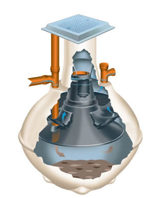
Septic tanks work in a similar way to cesspools – the foul waste ‘solids’ settle over time with gravity, and are partially broken down by bacteria (under a scum or crust on the surface). They are more efficient at separating the solid and liquid matters, employing a system of several chambers. The ‘refined’ liquid finally disperses into approved land drainage and percolates off into the ground. This process means that septic tanks can be smaller than cesspools and are cheaper to purchase. The solid waste matter that cannot be broken down further by bacteria accumulates as sediment at the bottom of the chamber, so periodic emptying will also be required by a suction tanker, despite ambitious claims to the contrary from some proud owners! The tank location must therefore allow sufficient access for the emptying truck, unless this is a DIY job that you particularly relish – in which case you may choose to recycle the waste, which by all accounts can make an excellent fertilizer. In Victorian times, the ‘nightsoilmen’ would empty privies in large towns to sell the contents for just such a purpose. The nature of the subsoil is an important factor to consider when designing private drainage systems. For example, in clay soil the percolation rate may be poor and an extensive system of perforated pipes over a larger area may be needed. Because the discharge is not entirely pure, the installation must be approved by the Environment Agency as well by Building Control. Today, more advanced large-volume septic tanks can be placed in an excavated pit just below ground level. These are environmentally friendly plastic or fibreglass units, some of which are effectively mini-sewerage treatment works that take the process one stage further, treating the liquid by-products so that they’re discharged as ‘clean’ water.
Further information
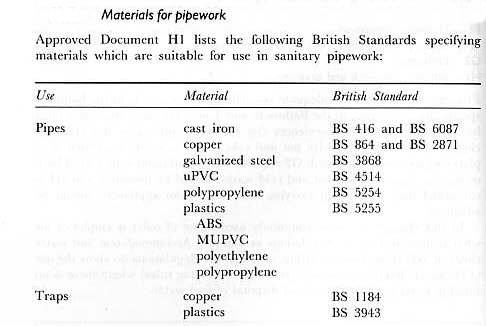
DRAINAGE - PIPE MATERIALS Pipes of the following
materials may be encountered: Cast iron Traditionally
used since Victorian times in places where high strength was needed, such as at
shallow depths under roads or foundations. Iron could withstand impact and
distortion, but the joints (often caulked with lead) could be prone to leakage.
Acid conditions, such as peaty soil, can accelerate corrosion. Clay Most drains constructed up to the 1950s will be of
fired clay, commonly in 100mm or 150mm (4in or 6in) diameters. These were
traditionally salt glazed with a glossy, water-resistant finish. But the salt
glaze manufacturing process caused vast amounts of pollution, so from the 1970s
on clay pipes were no longer glazed and these have proved to be just as good.
The joints were caulked with hemp yarn and cement mortar forced into the
sockets, which could seep inside (hence the old custom of dragging a ball of
sacking through newly laid pipes). Such rigid joints are extremely susceptible
to damage from ground movement. Clay
pipes remain popular today because of their resistance to chemical attack and
their modern flexible plastic couplings. Concrete
and cement fibre Mainly used for ‘big bore’ underground pipes of
150mm diameter and upwards, the weakness of concrete pipes is their
vulnerability to chemical attack from effluent on the inside (acids and
sulphates) or from the surrounding groundwater outside. Concrete pipes were
commonly jointed with cement mortar, which is unlikely to have remained
watertight. Their use should be restricted to carrying rainwater only. Now
mainly used for infrastructure projects and manufactured with protective
coatings. Asbestos
cement For generations, asbestos cement was a
wonder-material (light, strong, cheap etc) that seems to have been used
throughout the house, including soffits, flues, and even ceilings. More rarely,
it even found its way into underground pipes. Unfortunately, it was soon
discovered that asbestos pipes, like concrete, could deteriorate from attack by
chemicals. Some lasted only six years before developing serious leaks. They
must not be cut, drilled or disposed of without professional advice. Pitch
fibre Very popular around the mid-1960s, there will be many existing installations with pipes made of flexible ‘pitch fibre’ or asbestos fibre impregnated with sticky black pitch (bitumen tar). Unfortunately these could sometimes be a little too flexible, being squashed into an oval shape by the weight above if not properly laid.
MANAGING DISPUTES with contractors Mediation, litigation & terminating the contractor's employment If you find yourself bogged down with a
disagreement that can’t be resolved, you may have a genuine dispute on your
hands. This means an independent third party will need to be
appointed as adjudicator. Exactly who this nominated person should be must be
jointly agreed in the contract at the outset. It’s normally an experienced
chartered surveyor. Never appoint the person who designed your extension, since
it may turn out that some problems are due to bad design. Disputes
should always be dealt with promptly, as they’ll only get worse if ignored. If
the problem is due to building work that’s below par, and the builder has refused
to rectify it, then a good first course of action is to ask the Building
Control Officer’s opinion (although officially they may only be at liberty to
point out any contraventions of the Building Regulations). Otherwise, arrange
for an inspection by the nominated independent surveyor, who should be able to
produce a list of defects. A site meeting will need to be held to discuss it. If
both sides regard an issue as ‘a matter of principle’ it usually means they
feel bloody-minded enough to waste time trying to teach the other side a
lesson. At this point calm down! It’s silly to fritter away time and
money and to spoil a relationship for the sake of being proved right about a
few minor issues. Mediation
and litigation Of course shoddy workmanship, continually broken
promises and matters of dishonesty need to be directly addressed. The usual
solution is mediation, where a third party with expertise in the field attempts
to get both parties to agree a solution, making a judgement after listening to
both sides in turn. If
the builder still refuses to co-operate, you may be forced to resort to legal
advice to enforce the terms of the contract. Consumer legislation designed to
protect customers from unfair treatment may sometimes be appropriate. If formal
court proceedings are required, it helps to retain signed photographs of the
defects in question. It is important legally that you’re seen to have given the
builder every opportunity to rectify the problem. With a possible court
appearance in mind, try to keep a cool head and always be reasonably civil.
Reported episodes of ‘site-rage’ won’t reflect well on you in court, regardless
of extreme provocation. Alternatively, you may find that a solicitor’s letter
threatening action has the effect of a warning shot, saving both parties from
having to go to court, ultimately allowing the matter to be settled more
amicably.
Terminating
the contractor’s employment This is the weapon of last resort. As with the
unsavoury prospect of going to court, the mere threat to end the contractor’s
employment can sometimes be a sufficient wake-up call to him to get his ass
into gear. Termination is a major step, and only advisable if you’re stuck with
an impossible situation (and you haven’t paid them in advance). But you only have
the right to terminate if you can prove a serious breach has been committed by
the contractor, and that he has failed to put matters right after being
notified. For example: ·
Failure
to start work or to deliver any materials for a considerable
time after the agreed start date. This doesn’t apply if he’s just a bit late
starting. ·
Poor
quality workmanship, if much of the work is of exceptionally
poor quality and he has failed to make reasonable attempts to put it right
after being formally requested to do so. Poor
progress, if the project falls way behind schedule, with
many days of absenteeism on site, and it looks like the contract will have to
be significantly extended. He then fails to improve productivity despite formal
requests to do so. Other serious breaches might include the contractor
going bankrupt, or extremely aggressive or abusive behaviour. Don’t fall into
the trap of being provoked into spouting a lot of abuse back! No matter how
much you think they deserve it, a threatening attitude on your part not only
escalates the tension but could also expose you to a builder’s claim for loss
of profit. All subcontracted work is automatically cancelled when the main
contractor is terminated. This is Big Potatoes, and legal advice will be
needed. Once the dust has settled you’ll need to appoint another builder to
finish the job, for which they may well charge a premium.
|
|
|
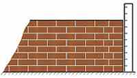
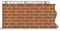
PART M Disabled Access The requirements for disabled access in Part M of the Building Regulations mainly apply to new houses, rather than home extensions. However it's not a bad idea to incorporate some of the design aspects, such as shallow gradient ramps to allow almost level thresholds and wider doors where possible. Such features are a real boon for kids, pram pushers, and oldies. But the regulations may also have some influence on the design of your immediate garden area. Specifically:- - Ramps built to the steepest permissable gradient of 1:12 should be no longer than 5 metres. However, ramps at shallower gradients such as 1:15 or 1:20 can be up to 10 metres long, without a landing. - Ramp should be at least 1500mm wide. - Normally steps are not allowed. But on steeply sloping sites it may be impossible to avoid having some steps, which must have a rise of no more than 150mm and a minimum width of 900mm.
Fireplace constructionSince Victorian times, there have been strict regulations governing the construction of fireplaces. It had been discovered from bitter experience (1666 and all that) that without such precautions hot coals and burning logs falling from merrily blazing fires could, rather inconveniently, set fire to nearby timber floors. Although it is unlikely that your new fireplace will be built into anything other than a concrete ground floor, the rules still apply since combustible floor coverings meeting the hearth can very easily be set ablaze. So current Building Regulations are reasonably rigorous in anything to do with fire safety. Briefly, the Building Regulations require:-
Obviously it is fairly sensible
to stipulate that fireplaces should be constructed from materials that protect your home from catching fire and
burning down. In practice the main danger area is to the room immediately in
front of the fireplace. This means that the
hearth to the floor at the front of the fireplace must be at least 125mm thick,
and made of an inert non-combustible material, such as concrete, brick or
stone. The hearth should project no less than 600mm beyond the
front of the fire opening, extending around the side returns to 150mm or more. As noted in chapter 9, the dark art of chimney and flue design can be surprisingly complex. Building a traditional open fire, or fitting a new heating appliance, means checking the implications for the flue, which must be the correct type for the fire. Essentially, in order to get a flue to draw properly a good supply of air is needed from the bottom, with small air bricks or pipes to outside. At the other end, the chimney pots need to be positioned clear of obstructions (such as the nearby roof ridge) to allow a reasonable flow of wind. As everyone knows, gas appliances must only be fitted by a competent CORGI- registered engineer, but it is only commonsense that any new heating appliance regardless of fuel type should be fitted by someone who knows what they are doing, and is suitably qualified to prove it.
WINDOWS QUESTION: Which parts of the Building Regs apply when you fit new windows ? ANSWER: Quite a few! A:
Structure B:
Fire Safety C:
Site Preparation and resistance to moisture E:
Resistance to the passage of sound (including the 2004 Amendment) F:
Ventilation K:
protection from falling, collision and impact L1A
Conservation of fuel and power (New Dwellings) L1B
Conservation of fuel and power (Existing Buildings) M:
Access to and use of buildings N:
Glazing – safety in relation to impact, opening and cleaning
PLUS HSE
Information Sheets: Construction Sheet No.2 (revised): Safe use of ladders Construction Sheet No. 10 (revised): Tower Scaffolds
|

e